After carefully reading through Skywatchers supplied instruction sheet i set about gathering some things together b4 i started, Philips/pozidrive screwdriver, set of grips paper towel etc.Whilst doing so i wondered if i should take a few pictures as i went along for my own peace of mind and also to expand further on the supplied instructions as the diagrams were somewhat lacking in enthusiasm.................. So here it is my Step by Step upgrade of a standard Heq5 to full Synscan GoTo .Removal of the standard Heq5 parts steps 1 through 5
Step 1
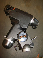
Get the mount infront of you so the dovetail top is on you left (pictured). Remove the 6 black screws you see holding an L shaped plastic motor cover, remove this cover to reveal the R.A & DEC motors.
This will do nicely now for keeping all your screws in one place. You'll notice that by taking off this motor cover there are two silver screws (arrowed) remove these two and flip the mount over to remove the other two in exactly the same place. Remove the curved cover and flip your mount back to show the brass motors.
Great stuff no more covers to remove ! press on........
 Step 2
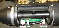
Now you have access to all the parts you will be removing, spin the mount so your looking at it as shown in the picture, This is the main circuit board.
Unplug all 3 plugs R.A - DEC - and one for the Control Panel. There is not much room above the circuit board and can be a fiddly place to access so take your time, this just cost you a few hundred £££ were not rushing this are we !!!
Spin the mount back around to the starting position.
 Step 3
Now we can unscrew the motors by removing 4 black screws on each motor, then lift the motors out being careful not to catch the plugs as you do so.
You'll notice the circuit board screws can only be accessed with the motors removed, but before we do that the Control Panel and onto step 4
 Step 4
Only two screws hold this in place so unscrew remove and feed the cable and plug ( the one you unplugged earlier) out again being careful not to snag any cables/plugs.
Turn the mount back around, then from the top looking down find and unscrew the two circuit board screws and slide it out. (second pictured down)

Step 5Fit the polar illuminator into the R.A shaft as pictured below, no screws here it just pushes in and the cable will feed down and out towards where the new circuit board will sit.
Slide the new circuit board in and screw it down, not too tight or you might crack the board, just tight enough for it not to wobble about by hand.

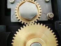
Step 6Now all you have left is a mount with no internal parts and just two brass gears looking back upto you (ignore the above image for now) However,,, the new Synscan motors require you to remove these two remaining gears.
Find the supplied alen key that will fit the two grub screws located on each gear, if u can remove these grub screws do so now. Clamp your grips over the top part of the gear ( the bit where the grub screws were) and pull them off the steel worm drive shaft.
This might take a bit of effort as they are well fitted or you could grab a hairdryer and warm the gear up to loosen it slightly as i did.
A good tip here is to use some tape around the ends of your grips so as not to damage/scratch the soft brass gear as u remove it, insulation tape or decorators masking tape will do just fine.

Gather up all the parts you have removed and place in a box or bag, but keep all the screws out apart from the 6 black motor screws you removed.

Fitting the Synscan parts to your Heq5 mount.Open the box containing the upgrade parts as im sure you've already done once before, and sort all the parts out ready, Motors, brass gears, Control panel, Circuit board, Polar illuminator, and the bag of screws / washers & allen keys.
Step 6Find the two new gears ( they are identical ) loosen the grub screws and slide onto the worm drive shafts. Dont tighten up yet.
Fit the new control panel. Easy to do just feed the cables through the hole and screw in the two screws you took out of the old one earlier. The panel with square itself to the mount body as u allign and tighten the screws.

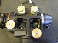
Position the mount so your looking at it as it is in the picture below, First find the DEC motor (it has the larger gear) and place it into the left hand space making sure u dont trap any of the wires underneath, feed the cable and plug under and out the DEC shaft.
Do the same with the R.A motor.
Find the 6 socket cap bolts and the 6 locking washers & 6 normal washers. The washers want to go onto the bolts in this order - Lock washer first normal washer 2nd.
Screw the bolts in so they hold the motors but do not tighten up fully yet.

Now your new motors and new gears are fitted you can get them nicely lined up so the gears mesh together properly. Too loose or too tight will cause uneven or accelerated wear. Look at the picture below once the motors have been moved around and the gears fit as shown tighten down the motor bolts but dont over tighten ! the mount body is alluminium and you dont wana bugger up any of the threads at this stage.
The two larger gears (with the grub screws) that are still loose remember ! can now be slid up or down the steel shaft so the gears are flush with each other. Holding the gear nice and flush with the motor gear tighten the grub screw square onto the flat part of the shaft first, then the second.
Now with the mount unlocked on both axis and before you put any grease on the gears turn the gears by hand, they should move freely with no binding. If the movement is stiff or un moveable re-adjust the motor and re tighten and test again. You'll get it just right after a few attempts.
Neat huh !
 Step 7
Plug all the connectors into there respective slots, printed on the circuit board is R.A & DEC respectively of there own plug. The other plugs will only fit there own socket so no confusion here.
It'll probably take a minute or two to feed the cables and plugs around each other and underneath the DEC shaft but thats ok, make it as neat as u think is needed and so your sure nothing will get caught or trapped when you refit the covers or when the mount is in operation.
Step 8Finished ! Do a final check, motor bolts tight, grub screws tight, grease the gears well with the supplied packet of grease.
Leave the two covers off and mount your heq5 Synscan mount onto the tripod, tighten it up as you would normaly do. Go out or stay in and test the synscan using the Manual to do so.
With the covers off you will be able to observe your motors are working properly and nothing is being trapped or is catching as the mount operates.
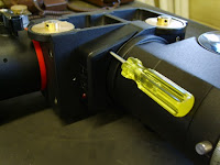
Here are a few more pictures of the finished upgrade. Enjoy your new mount and i hope you found this how to informative and interesting.


Thanks for reading people !!!